DC Motor: 6 V 250 RPM DC Motor
Microcontroller: ESP32-C3 Mini
Power Supply: Profuse DPS305U DC Power Supply
Oscilloscope: Rigol DS1054Z Oscilloscope 4 Channel 50 MHz
Logic Analyzer: To be added
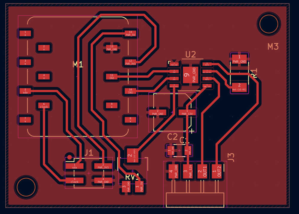
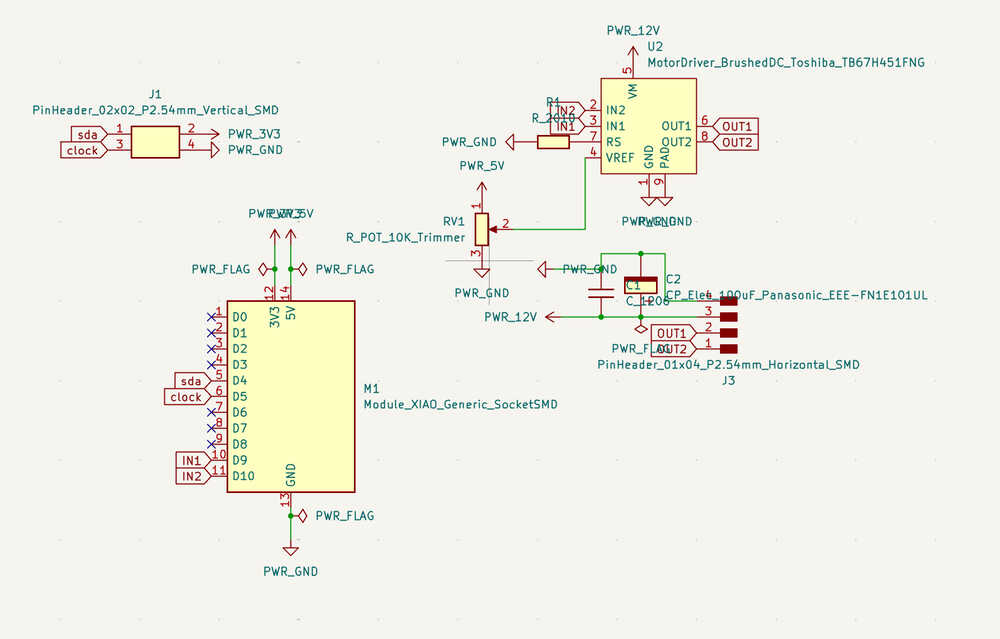
This PCB was designed as a motor-control board centered around the ESP32-C3 Mini and a motor driver IC. It routes logic-level control signals from the microcontroller to the driver, while separately carrying the higher-current motor power lines to the output connector. The design also includes power input headers, decoupling components, and pin headers for interfacing with the rest of the system. This allowed us to control the motor from code while keeping the power and control paths organized on a single custom board.
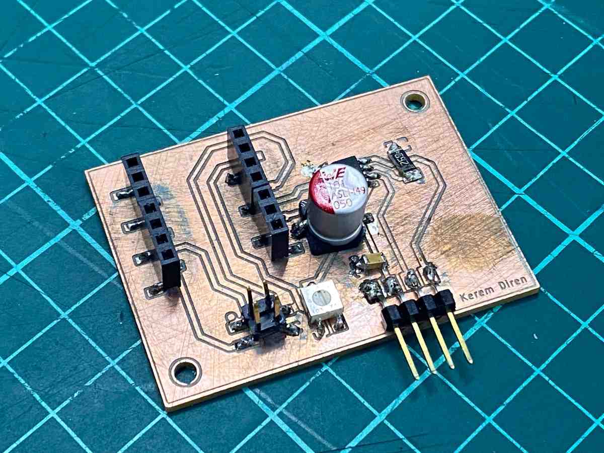
After completing the PCB design, we prepared the board for fabrication using the Roland SRM-20. The trace and outline files were exported from the design software and converted into toolpaths for milling. We first milled the copper traces on an FR-1 copper board using a fine engraving bit, and then changed the tool to cut the board outline. After milling, we cleaned the surface, removed burrs, and checked that the traces were properly isolated.
Once the board was ready, we soldered the components onto the PCB. This included the headers, motor driver section, passive components, and connector terminals. After soldering, we visually inspected the joints, checked for shorts or weak connections, and confirmed continuity before powering the board. When the board was fully assembled, we connected it to the motor and began testing the output behavior.
This is the code we used:
#include <Arduino.h>

const int IN1 = D9;
const int IN2 = D10;
int speed = 0;

void setup() {
    pinMode(IN1, OUTPUT);
    pinMode(IN2, OUTPUT);
    digitalWrite(IN1, HIGH);
    digitalWrite(IN2, LOW);
    Serial.begin(9600);
}

int a = 0;
void loop() {
    analogWrite(IN1, speed);
    a = Serial.parseInt();
    if (a != 0) {
        speed = a;
    }
}
After assembling the PCB, we connected the ESP32-C3 Mini, the motor output lines, and the external power supply to prepare the board for testing. The control pins from the microcontroller were routed to the motor driver section, while the motor was connected to the output terminal block. We then powered the circuit, uploaded the test code, and varied the PWM values through serial input to observe how the motor responded under different drive levels.
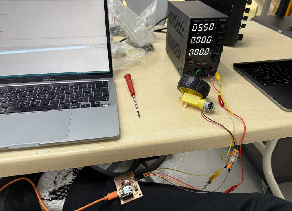
We measured the power consumption of the DC motor while controlling it with PWM values from the ESP32-C3 Mini.
The motor was supplied with a constant 5.5 V from the bench power supply, and the current was measured using a multimeter.
Power was then calculated using the formula P = V × I.
| PWM Value (analogWrite) | Voltage | Current | Power |
|---|---|---|---|
| 50 | 5.5 V | 0.031 A | 0.1705 W |
| 100 | 5.5 V | 0.085 A | 0.4675 W |
| 150 | 5.5 V | 0.125 A | 0.6875 W |
| 200 | 5.5 V | 0.140 A | 0.7700 W |
| 250 | 5.5 V | 0.150 A | 0.8250 W |
The results show that as the PWM value increased, the motor drew more current and consumed more power.
The motor behavior generally matched our expectations. At lower PWM values, the motor drew less current and consumed less power, while at higher PWM values the current and power consumption increased. The motor response became stronger as the PWM value increased, which is consistent with how a DC motor should behave when driven with a larger effective input.
Through this test, we learned how a PWM-controlled output device behaves electrically when the input signal changes. We observed that increasing the PWM value increased the motor’s current draw and overall power consumption. This group assignment helped us better understand the relationship between software control, circuit design, and the real electrical behavior of a motor-based output device.
To be added later after waveform capture and signal analysis.